Wi-Fi & IoT-Cloud
Dual-core ESP32 with 2.4GHz Wi-Fi and Bluetooth for sending sensor data to an IoT cloud platform.
A single integrated board combining an ESP32 microcontroller (Wi-Fi/Bluetooth), a long-range LoRa module, a battery-backed Real-Time Clock (RTC), an I2C interface with selectable 3.3V or 5V levels, two relay channels for controlling AC/DC electrical devices, and a microSD card slot for data logging.
The entire board operates from a single 220VAC power input, featuring a high-power switching power supply, surge and transient voltage protection, and fuse protection. The integrated supply supports laboratory and field applications without an additional external power module.
Key Design Highlight: The I2C interface is accessible through a stacked USB-A connector, allowing users to connect I2C sensors using a standard USB cable without requiring specialized connectors. The I2C supply voltage can be selected between 3.3V and 5V using a jumper, enabling direct connection to 3.3V sensors (SHT31, BME280, SEN66, etc.) and compatible 5V sensors without an external level-shifting module. This connector carries I2C signals; it is not a standard USB data port.
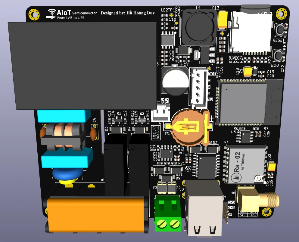
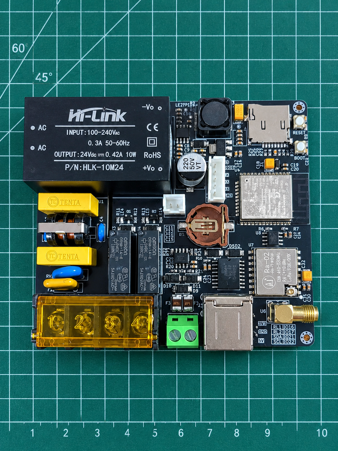
Dual-core ESP32 with 2.4GHz Wi-Fi and Bluetooth for sending sensor data to an IoT cloud platform.
Long-range LoRa communication. Reported lab-area testing: 1–1.5 km in an urban environment with trees and buildings; theoretical range: 10–15 km, depending on conditions.
VCC / SCL / SDA / GND on a stacked USB-A connector. Select the 3.3V or 5V supply with a jumper for compatible sensors.
Dedicated 5V / Rx / Tx / GND connector for serial sensors and UART communication.
DS3231M real-time clock with a CR1220 backup battery to retain time when main power is lost.
Omron G5NB-1A relays with optocoupler isolation for controlling AC/DC electrical devices.
On-board microSD slot for logging and storing data, including while the network connection is unavailable.
Integrated switching supply with surge and transient suppression and fuse protection.
The same board can operate as an IoT Node at a measurement point or as an IoT Gateway collecting data from multiple nodes.
As a Node, it reads I2C / UART sensors, timestamps measurements with the RTC and sends them to the Gateway over local LoRa. As a Gateway, it aggregates node data, buffers it on microSD when offline and uploads it to IoT Cloud over 2.4GHz Wi-Fi. The deployment model supports up to 256 nodes per Gateway.
Aggregate sensor data
RTC timestamps
microSD offline buffer
Remote monitoring
Data history
LoRa: theoretical range 10–15 km; reported testing 1–1.5 km in an urban environment with trees and buildings. Actual range depends on deployment conditions.
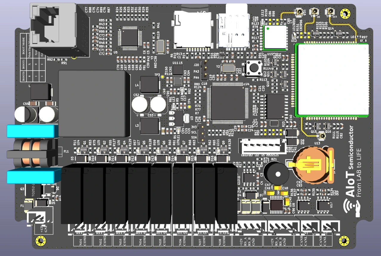
STM32F407-based controller for industrial pump monitoring, VFD control and data logging.
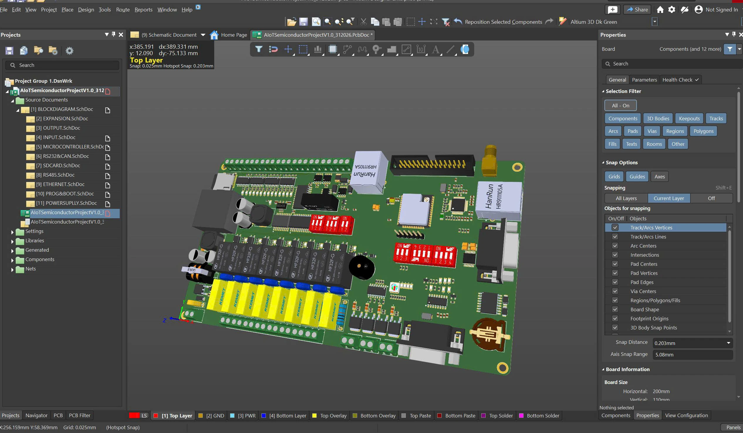
My personal ESP32 Datalogger hardware project, shown in Altium Designer.
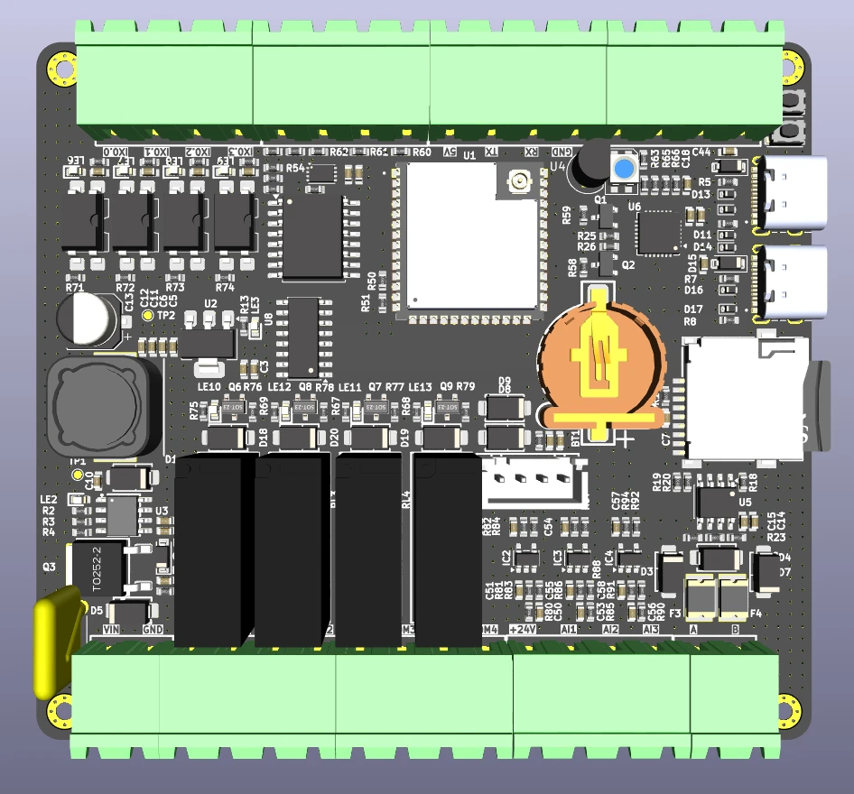
ESP32-S3 based PLC for industrial automation and IoT, with digital I/O, 4–20 mA analog interfaces and Modbus RS485.
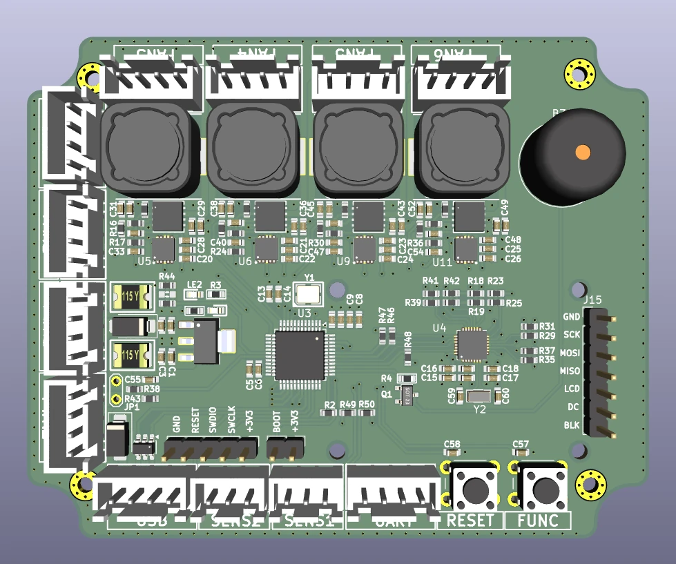
STM32F070-based intelligent PC fan controller with six PWM channels, four adjustable-voltage channels and USB control.
From the first question to the final fabrication handoff.
A considered approach to every connection.